In this tutorial, we’ll be discussing the OSI model in detail. If you are familiar with networking concepts and theories, chances are you have come across this model before.
What is the OSI Model?
International Organization for Standardization (ISO) developed the OSI model in 1984.
OSI model is an acronym for Open System Interconnect.
This model tries to explain how the data of an application passes through the device and out in the physical network using the seven conceptual steps or layers.
In simpler words, it explains how one application performs different steps to communicate its data to another application running on a different device.
The OSI model was created for creating a common industry standard, which could have helped inter-operability between different vendors.
Some believe that this model describes the network functionality well, while others believe today’s network is best described with more simplified models.
This model can be helpful when troubleshooting network or communication problems since it allows us to specify the general location or whereabouts of the problem.
Apart from that, it is a theoretical model that helps us understand the networking concepts better. While the OSI model was being developed, the internet adopted the TCP/IP and came in use widely.
Table of Contents
Layers of the OSI Model
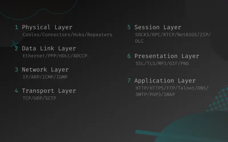
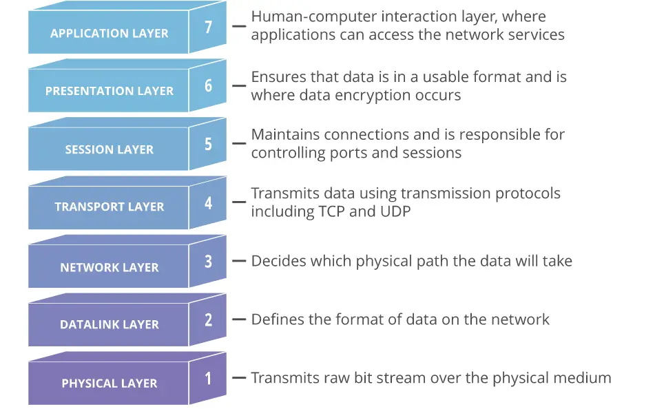
There are seven layers in the OSI Model. Each layer performs a certain functionality in data communication. Below are the seven layers listed according to their sequence:
- Physical Layer
- Data link Layer
- Network Layer
- Transport Layer
- Session Layer
- Presentation Layer
- Application Layer
Here’s an image describing the seven layers briefly (source: Wikipedia).
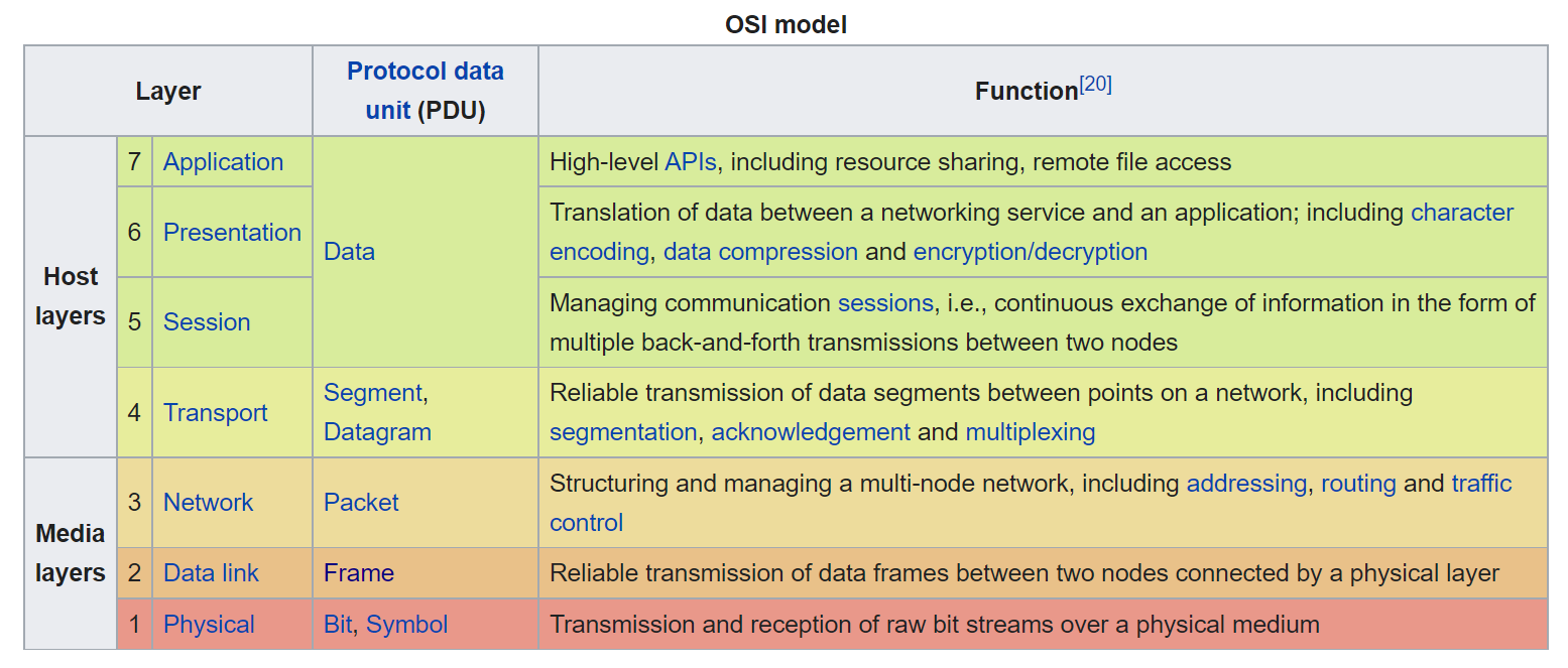
Now, we’ll describe each layer and their functionalities. Let’s begin with the Physical layer.
1. Physical Layer
Examples: Devices that operate at the physical layer – cables and connectors, hubs, network interface cards, repeaters, modems, etc.
This layer is what the name suggests. It’s everything physical in a network – the wires, the devices, etc. The raw data is sent and received as “bits” in this layer. The electrical, optical, or radio signal is converted into bits and transmitted through physical medium and vice versa.
Take, for example, you want to send a binary number (bit) i.e., 1 or 0 over the network. To do that, your network device will convert those digits into a high (1) or low (0) voltage and send them over the physical medium.
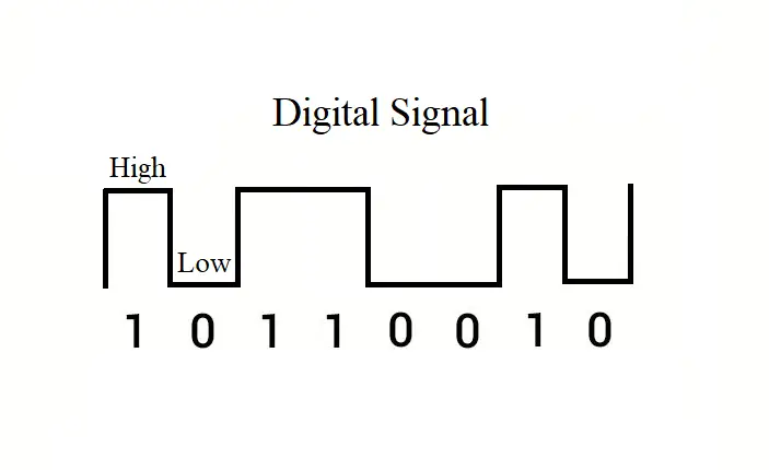
In simple words, when your device sends or receives some data, the device may do so using radio, electrical, or optical signals, and this task happens in this layer.
This layer would define different communication characteristics such as – voltage levels, signal timing, maximum transmission distances, modulation scheme, etc. This layer may also define transmission mode i.e., simplex, half duplex, or full duplex. Bit rate control is done in this layer as well.
This layer can receive data from the data link layer or send data to the data link layer in the OSI model. It is the first layer when it comes to receiving data from the internet, and it is the last when the data is sent from the host to the internet.
2. Data link Layer
Examples: Data link protocols are Ethernet, Point-to-Point Protocol (PPP), HDLC and ADCCP
This is the second layer of the OSI model. The data flows from the network layer to this layer before going into the physical layer.
As you know now, the physical layer converts the data into electrical, radio, or optical signals.
The network layer sends out data in the form of packets to the data link layer.
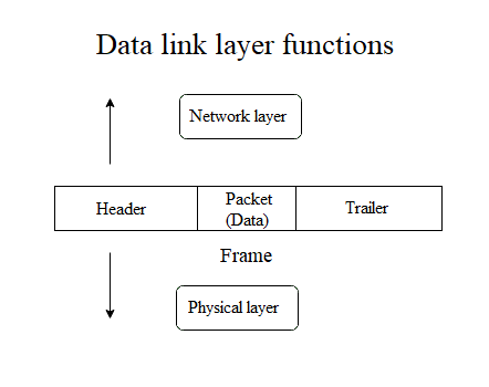
The data link layer adds certain properties to the packet using a header and a trailer.
The network layer packet encapsulated with the data link layer header and trailer is called a “frame”.
The header and trailer contain various information including the physical address of the source and destination. So, the data link layer mainly deals with the frames. These frames are then sent out through the physical layer. This is an important layer in the OSI model. Let’s learn about this layer in more detail.
Sublayers of the data link layer
There are two sublayers of the Data link layer. They are:
- Logical Link Control (LLC) layer
- Media Access Control (MAC) layer
We’ll learn briefly about the functionalities of these two layers in the next section.
Functionalities of the data link layer and it’s sublayers
In short, the main task of the data link layer is to prepare the data for the physical layer and enable node to node communication of data (frames). There are some specific services that the data link layer provides. The services are:
- Framing
- Physical addressing
- Flow control
- Access control
- Error control
Now, let’s take a look at each of these services or functionalities and what they mean.
Framing
The data link layer performs this task by inserting a chunk of information at once within a data unit called frame.
This layer takes the packet segments with the raw-bits information from the network layer and converts them into frames.
This is done by adding a header and a trailer to the packet information. This is shown in the image below.
The header contains the source and destination physical addresses. Some special bits are used in the beginning and end of each frame to ensure successful transmission.
Physical addressing
The network layer works with the logical addressing of the hosts with the IP addresses. The physical addressing is done in the data link layer with the MAC (Media Access Control) address.
Each and every network card has a physical address burned into them that cannot be changed physically. It is called the MAC address, and it is given by the vendor of the product.
The MAC addresses of the source and destination hosts are specified in the header of each frame. The physical addressing is done in the MAC sublayer of the data link layer.
Flow control
This is one of the most important functionalities of the data link layer. This functionality enables data transmission speed to be controlled and synced according to both the sender and the receiver. It is done in the Logical Link Control (LLC) sublayer of the data link layer.
Imagine a device can send 100 frames per second, while the receiver can only receive up to 50 frames per second.
If the sender sends the data at its maximum capability, the receiver will not receive all the data and a data corruption will occur. The data link layer ensures that the sender and receiver are communicating at the proper data transmission speed.
Access control
When multiple devices are connected through a common channel, which of them has the control of the communication channel is determined by the access control functionality. The Media Access Control (MAC) sublayer of the data link layer performs this function.
Take a scenario where you have 10 devices that are connected in a bus network (uses a common channel). Let’s say device A, B, and C send data over the network at the same time. If this happens, there will be collisions of data within the channel most of the time, and all the data will be discarded. The data link layer ensures that this collision does not occur frequently. The access control functionality allows a specific device to have control over the whole channel for a certain period of time. This way the collision is avoided.
Error control
The data link layer also performs the crucial task of error checking, i.e., it ensures that the received data are received without any errors.
During data transmission, many unexpected events might alter or corrupt the data before it reaches the destination.
To ensure the data integrity, there must be some form of error checking capabilities. The data link layer performs error checking by calculating some special value from the bits of the frames both in the sender and receiver side of the communication. If these values do not match each other, there must have been some kind of error while the data was in transmission.
3. Network Layer
Examples: The network layer includes protocols such as the well known IP (Internet Protocol), Address Resolution Protocol (ARP), ICMP (Internet Control Message Protocol), Internet Gateway management Protocol (IGMP)
In this layer, the data from the transport layer gets attached with a header and it is called a packet.
The header contains the logical address or the IP address of the source and destination. The routing of the packets from one network to another network is also performed using the protocols in this layer.
We have covered how the network layer and the transport layer come together creating the internet, along with different concepts about the IP addresses in our other article What Are IP Addresses: Basic Concepts and Terms Explained (Versions, Type, Subnetting, Ports). Take a look if you want to dig deep.
Some the functionalities of this layer are:
- Logical addressing: This is where the IP addresses are used to logically separate different hosts. IP addresses work like a literal address for the devices on the network. They are used to send data to the intended receiver. There are two versions of the IP addresses. The IP version 4 (IPv4) and the version 6 (IPv6).
- Routing: The routing of the data packets is also done in this layer. This task is performed by the routers. They all have a routing table that indicates where the next destination should be for the packets.
- Fragmentation: The sent packets are fragmented according to a limit size before sending. The packets are merged together once it arrives at its destination. This way the data communication is faster and more reliable.
4. Transport Layer
Examples: Transport layer examples are TCP (Transmission Control Protocol), UDP (User Datagram Protocol) and SCTP (Stream Control transmission Protocol).
In the OSI model, the 4th layer is the transport layer and this is where communication service is provided to the running applications. It is called the Heart of the OSI Model.
This layer takes in data from the network layer and sends them to the session layer or vice versa. The transport layer is the layer where the complete data is received and this is the layer which acknowledges the complete transmission of the data.
Re-transmission occurs if any error is found in the data. Data unit is referred to as segments in this layer.
Functions of the Transport layer
The transport layer mainly performs two important functionalities:
- Service-point addressing
- Segmentation and reassembly
Let’s learn about these functions briefly.
Service-point addressing: Ports
The transport layer works within the OS (Operating System) of a device.
A single machine/computer might have multiple programs or applications or services running on it that are connected to the internet.
These programs might require communicating different messages. This is accomplished with Ports. The port information is added to the data from the session layer in the transport layer of the OSI model.
Read more about the ports in this article in the ports section.
Segmentation and reassembly
The transport layer also divides the data from the previous layer (session) and puts them into small data units called segments.
Each of the segments is attached with a sequence number and sent to the receiver. After the receiver completes receiving all the segments, they are put back together using the sequence number of the segments.
Services/protocols of the Transport layer
The transport layer provides two specific communication services. Connection oriented service and connectionless service. There are two transport layer protocols. The TCP (Transmission Control Protocol) and UDP (User Datagram Protocol).
Connection oriented service/protocol
The TCP protocol is a connection-based protocol, meaning it requires establishing a connection between the source and destination before data transmission.
It is reliable and implemented where data accuracy and continuity are important such as downloading files.
In this case, the data is segmented and sent from the sender’s side, while the data is received and put back together at the receiver’s side. The segments might be sent and received in random order; however, they are arranged in the correct sequence when putting back all of them together to get the original file.
Connectionless service/protocol
UDP is a connectionless protocol and it is used where speed is the main concern.
No prior connection establishment steps are required in this type of communication. Sent data is not required to be put back in a sequence.
The receiver does not acknowledge the receipt of data and the sender does not wait for the acknowledgment from the receiver as well.
This ensures faster speed in communication. A proper example would be online multiplayer video games.
5. Session Layer
Examples: Session layer implementations include ZIP (Zone Information Protocol), AppleTalk Session Protocol, SCP (Session Control Protocol), NetBIOS (network basic input/output system), DLC (data link control), PAP (printer access control), SMB (server message block), RPC (Remote Procedure Call), RTCP (RTP Control Protocol), SOCKS (Socket Secure), and more.
It is the 5th layer in the OSI model. This layer provides the functionality of establishing a session in data communication.
A session acts as a checkpoint between data transfers. The layers that are below this layer (Application and Presentation layers) do not include the concept of connecting with a different machine, whereas the previous layers (Transport, Network, Data link, and Physical layers) just send data individually without the concept of a session or a connected data flow.
The session layer connects these layers by managing sessions and synchronizing data flows.
One of the most popular protocols that work in this layer is the SSL (Secure Sockets Layer) protocol.
Apart from that, this layer also manages authentication and security services. For example, when you are logged into a messenger, you do not have to authenticate every time you send a text. You already have an authenticated session that you can continue. Similarly, when a download is started, the client creates a session with the server. If the download fails midway, you could have the option to resume from a previous checkpoint, until the session expires.
The functionalities of this layer are:
- Session management: The session layer could establish, continue an established session, or terminate the session.
- Synchronization: This functionality allows the data transmission to have some checkpoints to go back to in case of failure or some unexpected errors.
- Dialog control: This layer also identifies and allows two systems to communicate using half-duplex or full-duplex methods.
6. Presentation Layer
Examples: Presentation layer protocols include SSL (secure sockets layer), TLS (transport layer security), MP3 (formally MPEG-1 Audio Layer III or MPEG-2 Audio Layer III), GIF (Graphics Interchange Format), PNG (Portable Network Graphics), etc.
This is the 6th layer of the OSI model.
Imagine the variety of applications that are run on operating systems these days – all of them deal with different types of data.
The main task of this layer is to translate the network data or syntax to presentable data for different applications. In short, this layer provides independence from different data representation from the application layer and sends them to the network layer after translation.
The presentation layer is also called the syntax layer.
This layer performs:
- Translation: As explained above, this layer performs the translation or formats the data according to the syntax and semantics the application layer accepts.
- Encryption/Decryption: The presentation layer also deals with the encryption or decryption that the application layer demands.
- Compression: Data compression is also performed in this layer, which decreases the number of bits that are required to send over the network.
7. Application Layer
Examples: Protocols included in the application layer include HTTP (Hypertext Transfer Protocol) , HTTPS (Hypertext Transfer Protocol Secure), FTP (File Transfer Protocol), Telnet (Teletype Network Protocol), DNS (Domain Name System), SMTP (Simple Mail Transfer Protocol), POP3 (Post Office Protocol 3), IMAP (Internet Message Access Protocol), and more.
This is the 7th or the final layer of the OSI model.
In brief, this is the layer where the human-computer interaction mainly occurs.
The layer comes into play whenever the user decides to perform some network related activities such as sending a message or email, downloading a remote file, etc.
The apps we use every day – browsers, email clients, Discord, Slack, etc. use the application layer protocols to perform the network tasks.
Putting it all together: Data flow in the OSI Model
We have learned about all the layers of the OSI model individually. Now, in this section, let’s learn how the data moves from one layer to another layer and how the communication process is done. Take a look at the image below:
Sender’s side
- It all starts in the application layer with the human/application deciding to perform a communication or a data transmission. Then the data from the application layer moves down the layers.
- The presentation layer converts the application layer data into a format that is suitable for transferring over the network.
- The session layer establishes a session for the connection and may maintain this session for continuous data transmission.
- Then the data from the session layer moves down to the transport layer. This layer adds the necessary port information with the data.
- After that, the data with the port information comes down to the network layer. In this layer, the IP address information is included in the IP header. The IP header consists of both the sender’s (source) and the receiver’s (destination) IP addresses. Apart from that, the header also includes information about the IP version, time-to-live, etc.
- After the network layer, the data comes to the data link layer. This layer adds the necessary header and trailer to the network layer packet and creates units of data called frames. The headers of the frames contain the physical addresses of the source and the destination (MAC addresses).
- The last layer is the physical layer, from where the frames are sent as bits using the electrical, radio, or optical signals.
Receiver’s side
The data receiving process is exactly the opposite of how the data is sent from the sender’s side. In this case, the process starts with the physical layer receiving streams of raw bits as electrical, radio, or optical signals. The data then moves up the layers and finally reaches the application layer where the intended user or application receives the data.
The TCP/IP Model
While the OSI model was in development the internet quickly adapted the TCP/IP model of communication. TCP/IP stands for Transmission Control Protocol (TCP) and Internet Protocol (IP), and is also called the Internet Protocol Suite.
This model has only four layers, and it is much simpler than the OSI model. We will briefly talk about this model and how it relates to the OSI model so you know better. The four layers of this model are:
- Link Layer
- Internet Layer
- Transport Layer
- Application Layer
In this model, the physical layer and the data link layer of the OSI model has been merged into the Link Layer.
Furthermore, the TCP/IP model incorporates the session layer, presentation layer, and the application layer of the OSI model together in the Application Layer.
This model functions similarly as the OSI model. Take a look at the image below to understand the data flow in the TCP/IP model better.
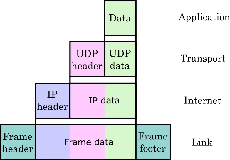
As you can see from the image, the TCP/IP model also works in pretty much the same way as the OSI model.
- The data from the application layer is attached with the TCP or UDP header in the transport layer.
- The internet layer adds the IP address information in the IP header.
- The IP header is attached to the IP data (data from the transport layer).
- After that, the link layer creates the frame using additional header and trailer.
Conclusion
The OSI model serves as a reference model which helps us understand data communication and transmission better.
In this article, we covered some of the basic concepts of the OSI model and the seven layers of the model. This article is just an introduction.
There is much more information you can learn about the OSI model.
For example, you could learn how the functionalities in each layer are performed. There are many resources on the internet for learning more. If you read the article thoroughly, you should also be able to understand the basics of how the internet works by now.
We hope you liked the article. If you have any questions or comments for us, leave them down below, and we’ll get back to you as soon as possible.
